Functional Features
Equipment data acquisition uses two synchronous 16 – bit high – resolution low – noise analog – to – digital converters, and the maximum sampling rate of dual – channel synchronous sampling is 2.5MHz.
It can expand and scan electrochemical microscopic functions.
The scanning speed of cyclic voltammetry is 1000V/s, and the potential increment is 0.1mV. The measurement frequency of AC impedance can reach 3MHz, and the frequency of AC voltammetry can reach 10KHz.
Technical Parameter
| Potentiostat | |
|
Structure |
Zero – resistance ammeter.
2, 3, 4 – electrode structure. Floating ground or earth |
| Maximum Potential Range | ±10V |
| Maximum Current | ±250mA continuous, ±350mA peak |
| Slot Voltage | ±13V |
| Potentiometer Rise Time | Less than 1 μs, typically 0.8 μs. |
| Potentiostat Bandwidth | 1 MHz (-3 dB). |
| Applied Potential Range | ±10 mV, ±50 mV, ±100 mV, ±650 mV, ±3.276 V, ±6.653 V, ±10 V. |
| Applied Potential Resolution | The resolution of the potential range is 0.0015. |
| Applied Potential Accuracy | ±1 mV, ±0.01% of full – scale range. |
| Applied Potential Noise | < 10 μV, both root – mean – square. |
| Measurement Current Range | +10 pA to ±0.25 A, 12 ranges. |
| Measurement Current Resolution | The resolution of the current range is 0.0015, with a minimum of 0.3 fA. |
| Measurement Current Accuracy | The current sensitivity is greater than or equal to 1 e – 6 A/V with an accuracy of 0.2%. Other ranges are 1%. |
| Input Offset Current | < 20 pA. |
| Galvanostat | |
| Constant Current Range | 3 mA – 250 mA. |
| Applied Current Accuracy | ±20 pA, with an accuracy of ±0.2% for currents from 3 – 3 – 7 A, and 1% for other ranges. |
| Applied Current Resolution | The resolution of the current range is 0.03. |
| Measurement Potential Range | ±0.025 V, ±0.1 V, ±0.25 V, ±1 V, ±2.5 V, ±10 V. |
| Measurement Potential Resolution | The resolution of the measurement range is 0.0015. |
| Electrometer | |
| Input Resistance of the Reference Electrode | 1e12 ohms. |
| Waveform Generation and Data Acquisition System | 10 MHz. |
| Input Bias Current of the Reference Electrode | At 25 °C, < 10 pA. |
| Waveform Generation and Data Acquisition System | |
| Fast Signal Generation New Speed | 10 MHz, 16 – bit resolution. |
| Fast Data Acquisition | 16 – bit resolution ADC, two – channel synchronous sampling, sampling rate 2.5 M Hz. |
| External Signal Recording | 1MHz |
| Experimental Parameters | |
| Scanning speed of CV and LSV | 0.000001V/s to 10000V/s |
| Potential increment during scanning | 0.1mV when the scanning speed is 1.000V/s |
| Pulse width of CA and CC | 0.0001 to 1000sec |
| Minimum sampling interval of CA and CC | 0.4 μs |
| Integrator | CO analog integrator |
| Pulse width of DPV and NPV | 0.001 to 10sec |
| SWV frequency | 1 to 100kHz |
| Minimum sampling interval of i – t | 0.4 μs |
| ACV frequency range | 0.1 to 10kHz |
| SHACV frequency range | 0.1 to 5kHz |
| FTACV frequency range | 0.1 to 50Hz, can simultaneously acquire fundamental wave, second – harmonic, third – harmonic, fourth – harmonic, fifth – harmonic, and sixth – harmonic ACV data |
| Electrochemical impedance | 0.0001 to 3MΩ |
| Electrochemical impedance amplitude | 0.00001V to 0.7V (both RMS values) |
| Other parameters: | |
| iR drop compensation mode: | automatic or manual |
| Current measurement deviation | full – scale range, 16 – bit resolution, 0.003% accuracy |
| Potential measurement deviation | ±10V, 16 – bit resolution, 0.003% accuracy |
| Potential input | external potential input |
| Analog output | can achieve analog output of potential and current |
| Controllable potential filter | cut – off frequencies of 1.5MHz, 150kHz, 15kHz, 1.5kHz, 150Hz, 15Hz, 1.5Hz, 0.15Hz |
| Controllable signal filter | cut – off frequencies of 1.5MHz, 150kHz, 15kHz, 1.5kHz, 150Hz, 15Hz, 1.5Hz, 0.15Hz |
| Rotating electrode control voltage | 0-10V signal is used for rotational speed ranging from 0 to 10000 rpm, with 16-bit resolution, an accuracy of 0.003%, and it requires certain rotating electrode devices to function. |
| Control digital input / output | digital input / output lines can be controlled through macro commands |
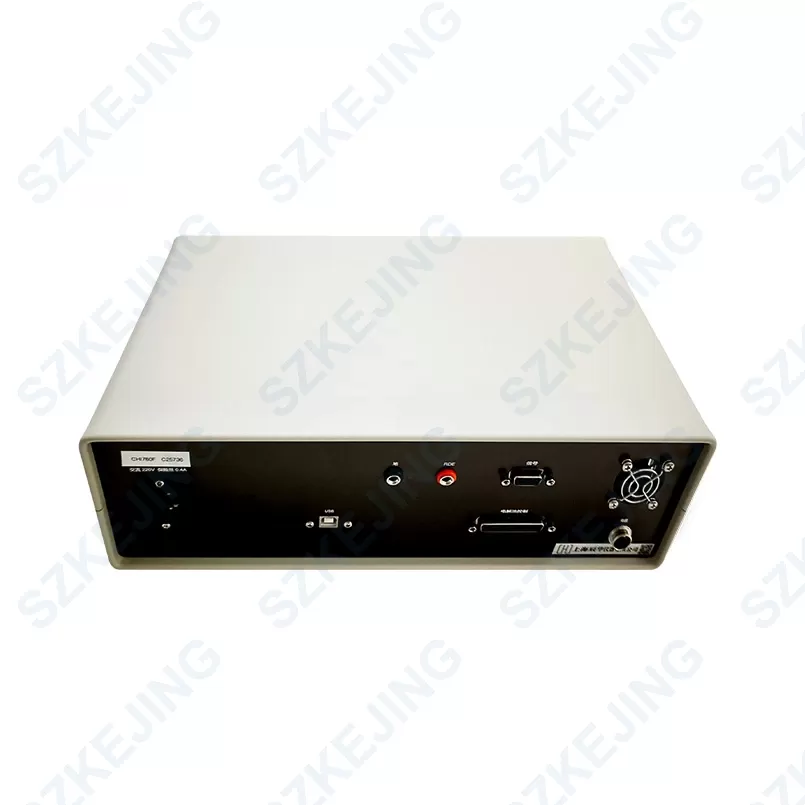
| Communication method | USB port data communication |
| Electrolytic cell control | nitrogen, stirring, knocking (a special electrolytic cell system is required) |
| CV digital simulator and synthesizer | User-defined reaction mechanism |
| Communication impedance simulator and fitting tool | available |
| Maximum data length: | selectable from 256K – 16384K |
| Measurable function | Cyclic Voltammetry (CV) Linear Sweep Voltammetry (LSV) Staircase Voltammetry (SCV) Tafel Plot (TAFEL) Chronoamperometry (CA) Chronocoulometry (CC) Differential Pulse Voltammetry (DPV) Normal Pulse Voltammetry (NPV) Differential Normal Pulse Voltammetry (DNPV) Square Wave Voltammetry (SWV) Alternating Current (including phase-sensitive) Voltammetry (ACV) Second Harmonic Alternating Current (phase-sensitive) Voltammetry (SHACV) Fourier Transform Alternating Current Voltammetry (FTACV) Current-Time Curve (i-t) Differential Pulse Amperometry (DPA) Dual Differential Pulse Amperometry (DDPA) Triple Pulse Amperometry (TPA) Integrated Pulse Amperometric Detection (IPAD) Controlled Potential Electrolysis Coulometry (BE) Hydrodynamic Modulation Voltammetry (HMV) Sweep-Step Hybrid Method (SSF) Multiple Potential Step Method (STEP) Potentiostatic Intermittent Titration Technique (PITT) Alternating Current Impedance Measurement (IMP) Alternating Current Impedance-Time Measurement (IMPT) Alternating Current Impedance-Potential Measurement (IMPE) Chronopotentiometry (CP) Current Scanning Chronopotentiometry (CPCR) Multiple Current Step Method (ISTEP) Galvanostatic Intermittent Titration Technique (GITT) Potentiometric Stripping Analysis (PSA) Electrochemical Noise Measurement (ECN) Open Circuit Potential-Time Curve (OCPT) RDE Control (0-10V output) CV Simulator for Arbitrary Reaction Mechanisms Alternating Current Impedance Digital Simulator and Fitting Program |
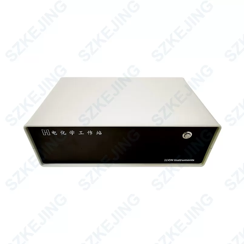
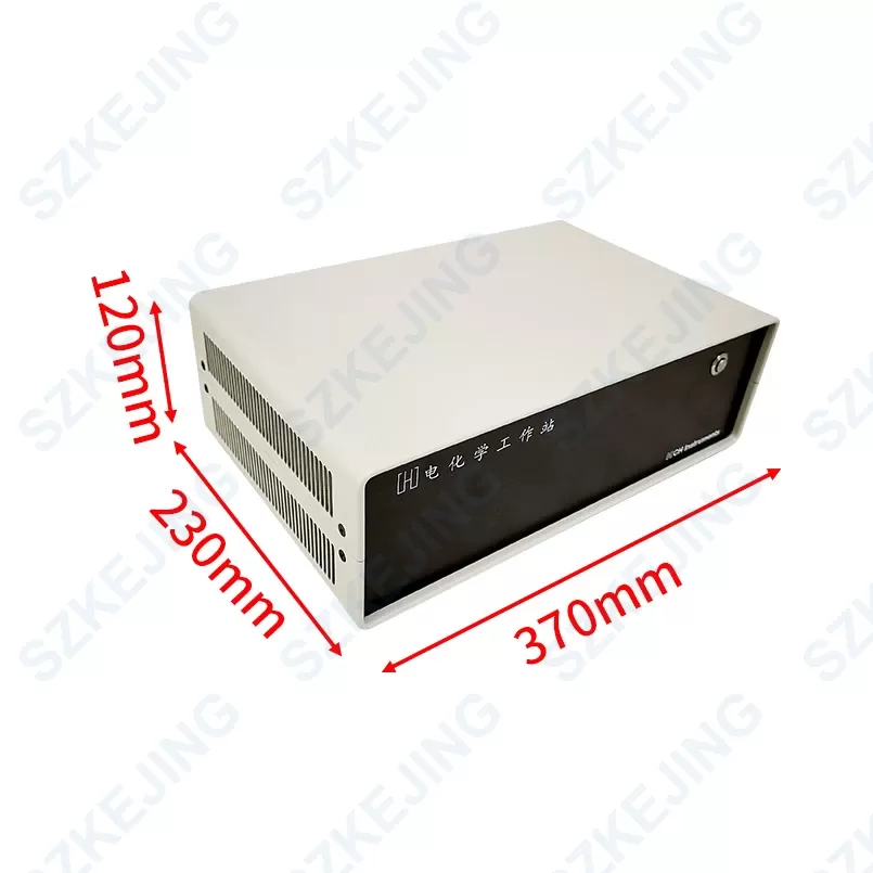
| Dimension | W 370mm*D 230mm*H 120mm |
| Weight | 4KG |

